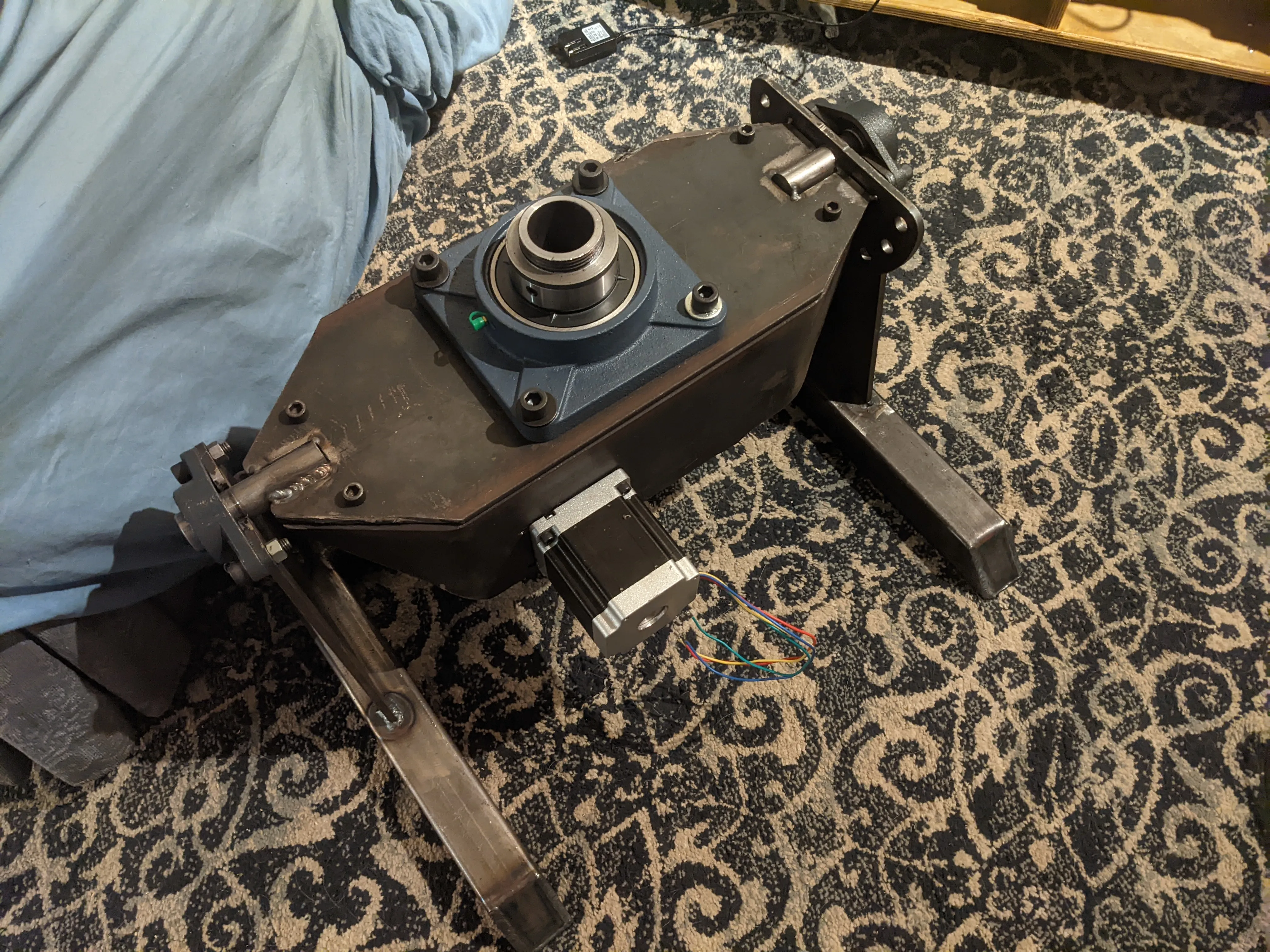
Built a welding positioner capable of supporting several hundred pounds with infinitely variable rotation speed and 90+ degree tilt
As part of a future project I determined the need to perform “round” welds.
The design requirements for this project were to:
- Support several hundred pounds, because why not?
- Contain a through-bore greater than 1.5”
- Rotate in a speed controlled manner
- Tilt through many angles
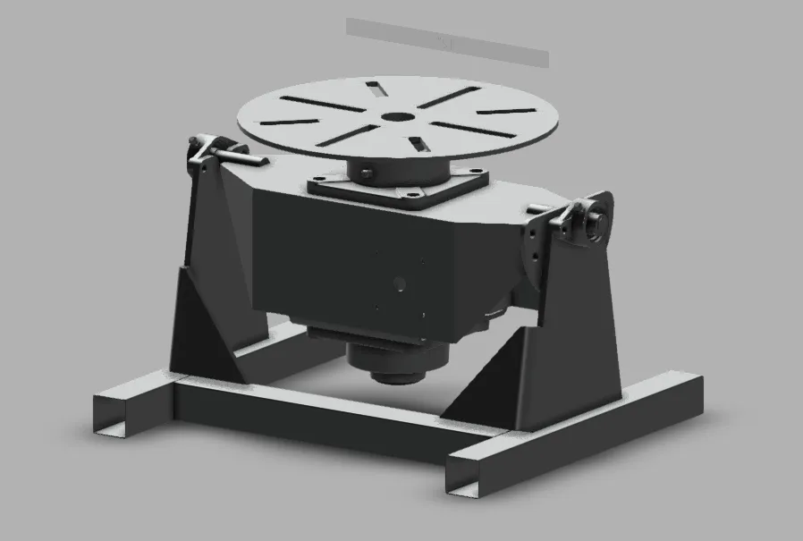
I wanted to become more familiar with Fusion 360 sheetmetal tools. The design started with the “wings” - the two side plates with bend edges, and bending the bottom tab in to support the bottom bearing.
Intentionally I tried to use a single material source, 1/4” by 8” flat “bar” which was used for everything and cut on a plasma table.
This was iterativly checked against and refined with the internal mechanism. I remember an exhausting process of just staring at the CAD model trying to get directions of motion aligned with physical sizes.
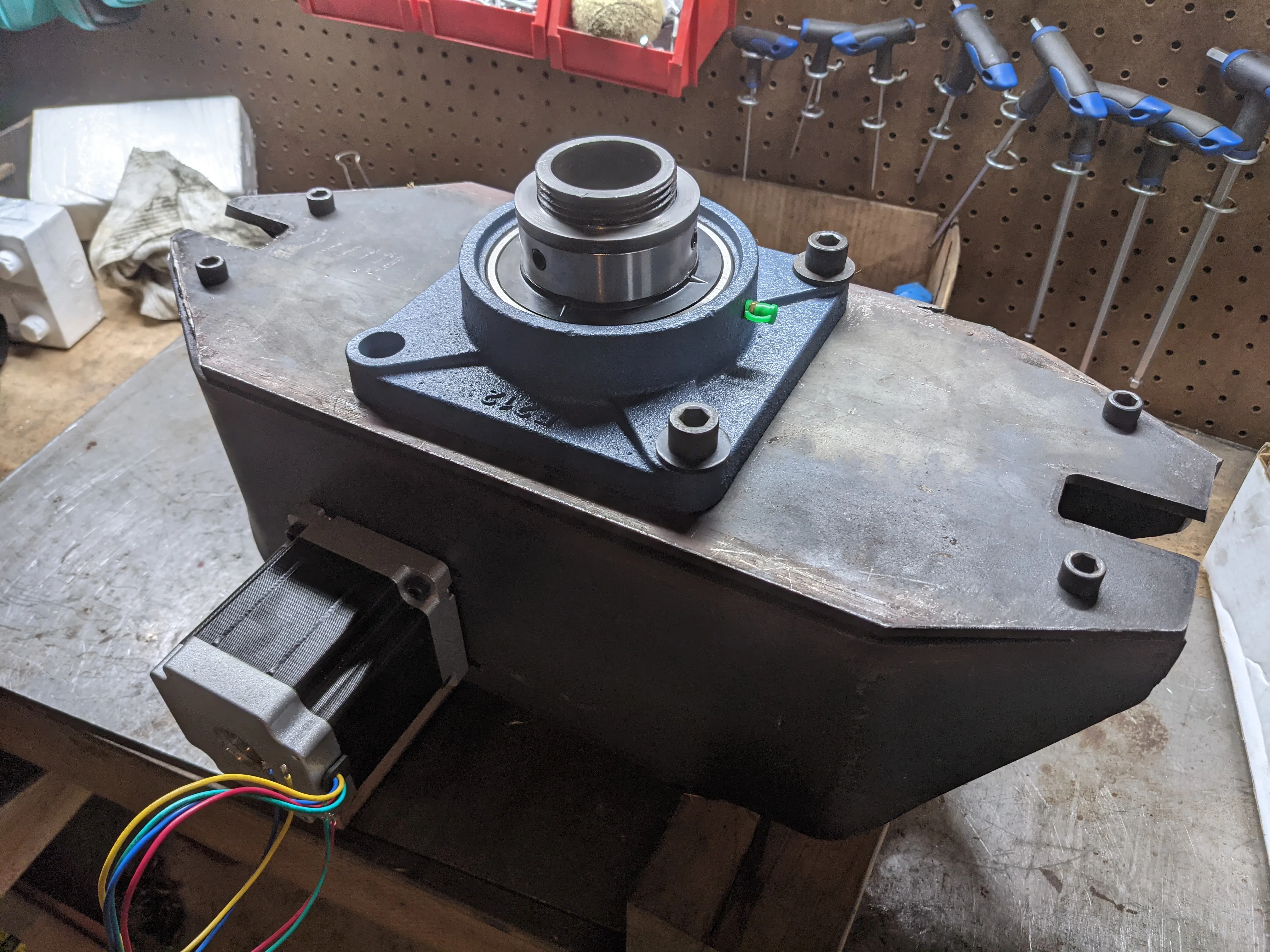
I call this process “pinning”. At a certain point I select a bearing (based on through bore + wall thickness required for expected load) and that decides a body shape. The body shape and load requirements dictate that I need to transfer the motion ONTO the large diameter shaft, which usually requires a pulley, and the motion requires no backlash which drives to a timing belt. The expected load and expected face size drive a torque, which combines with body shape (aka max pulley size) drives a belt width etc etc etc
By chasing down and pinning requirements
- THIS bearing
- THIS belt
- THIS pulley
- THIS gearbox I eventually end up with some “black boxes” of functionality which can be pinned in place. I modeled these shapes up in CAD and jiggled them around
One key insight that finally clicked everything into place is that I could split the motor and gearbox through the body, and we end up with this ungainly shape
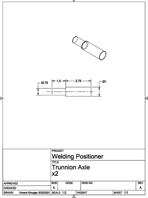
The only CNC tool I had at the time was a plasma cutter, so I had to create drawings for myself to follow for the manual machining
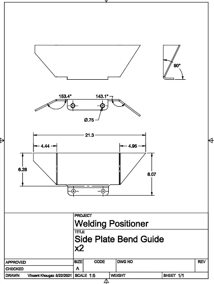
And for the side plate I decided to cut them out using my plasma cutter, then bend them with my (side project with a video) press-brake
I created drawings to locate the bends and bent away
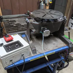
Fabrication was fairly straightforward, though I made the decision to temporarily bolt the top on rather than creating the envisioned weldment
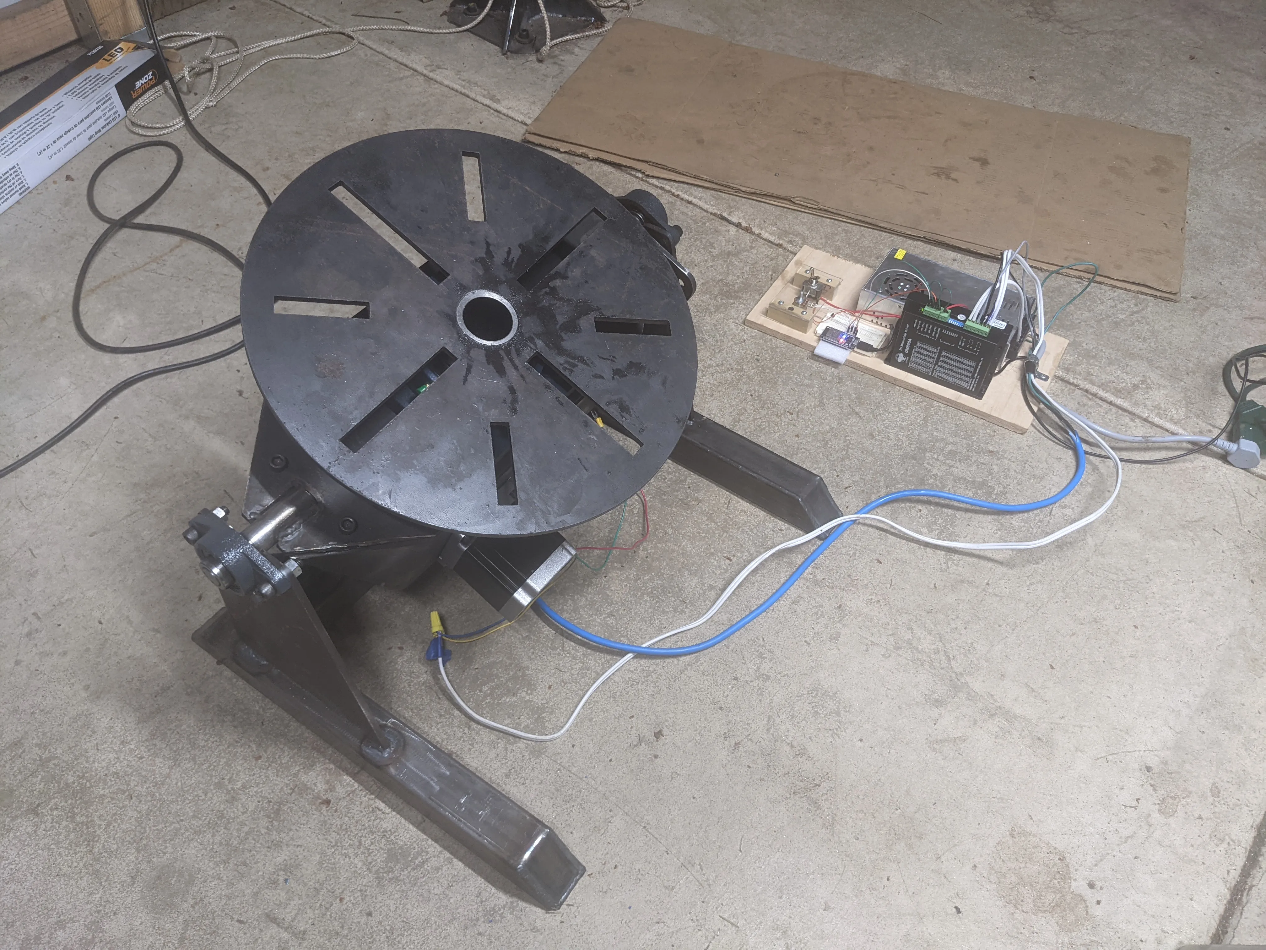
I rough prototyped the electronics on plywood first to prove it out and develop the software
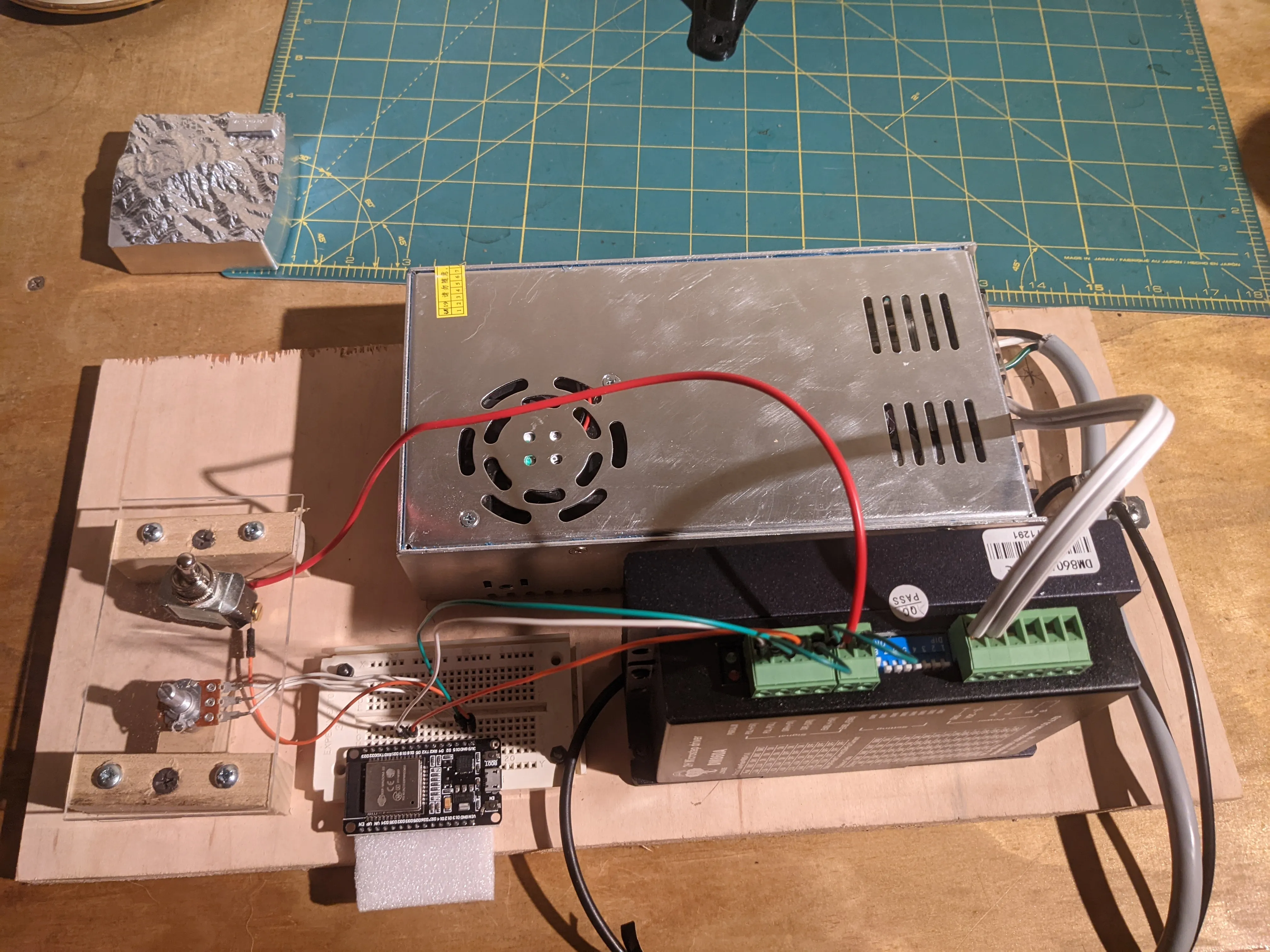
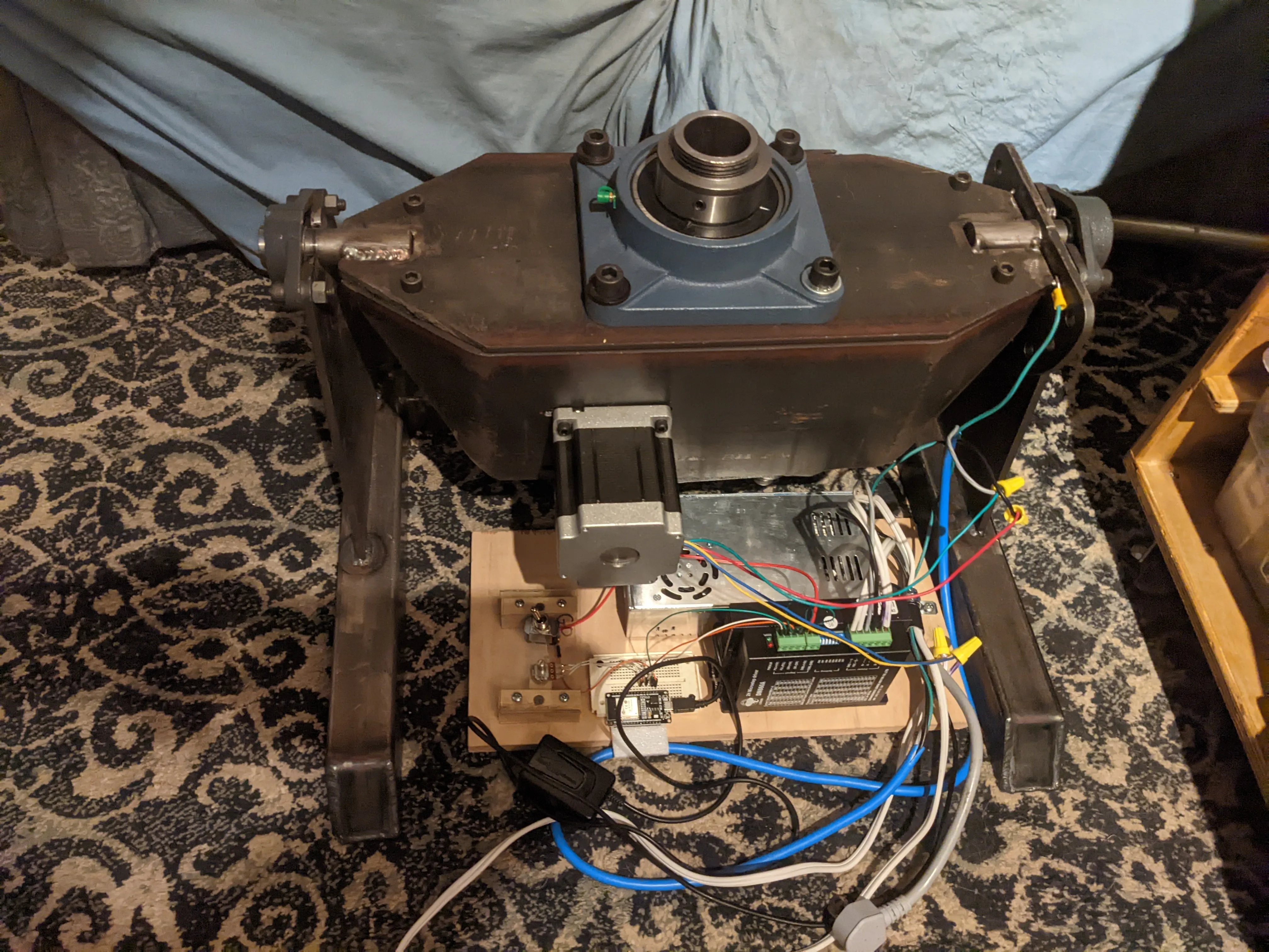
and some of the first full inegrations happened in my office rather than my shop
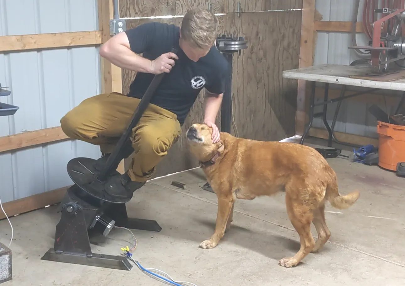
It proved quite robust in practice, well able to be ridden. One of my shop thesis’ is to optimize for joy, and boy howdy anything I can ride certainly inspires that joyful grin
This was one of my first control cabinets and was a bit rough with respect to cable routing and… best practice for cabinet design.
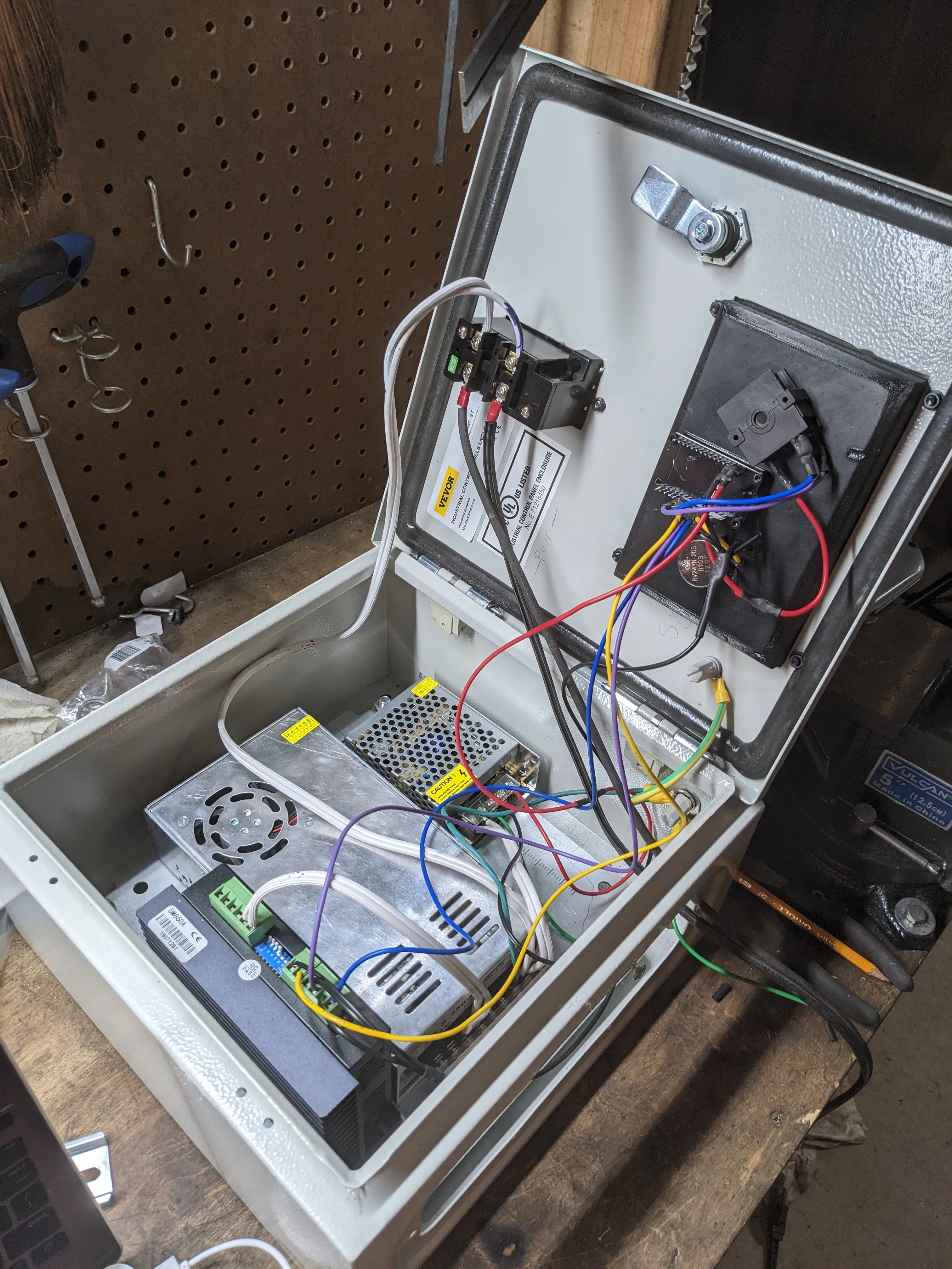
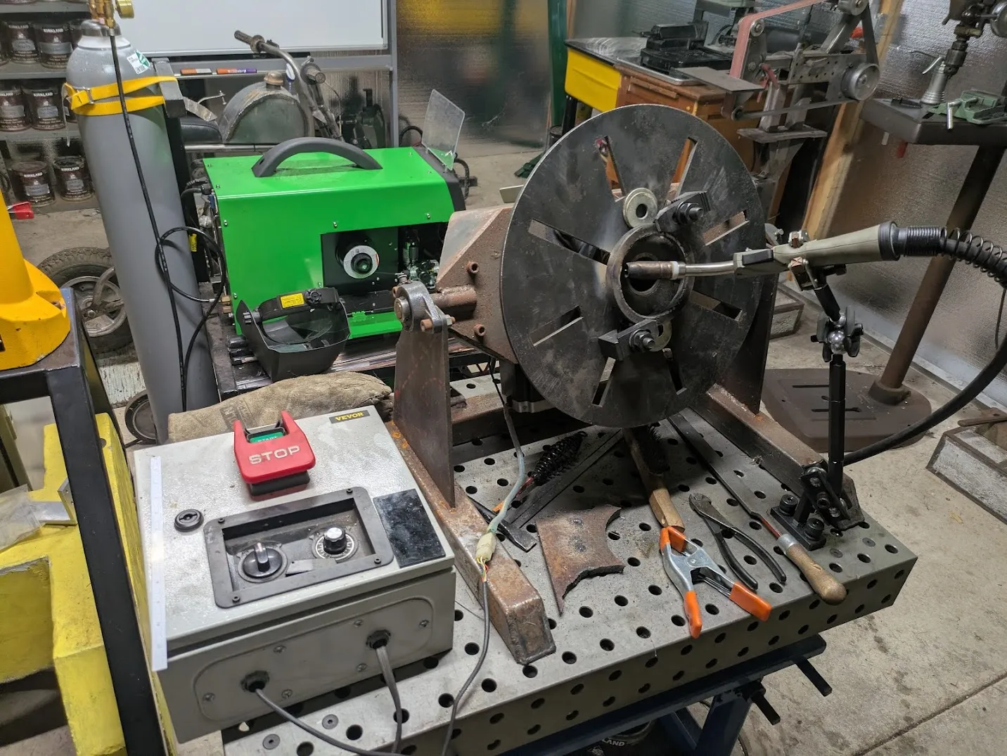
Though I must say the final design has ended up rather tidy.
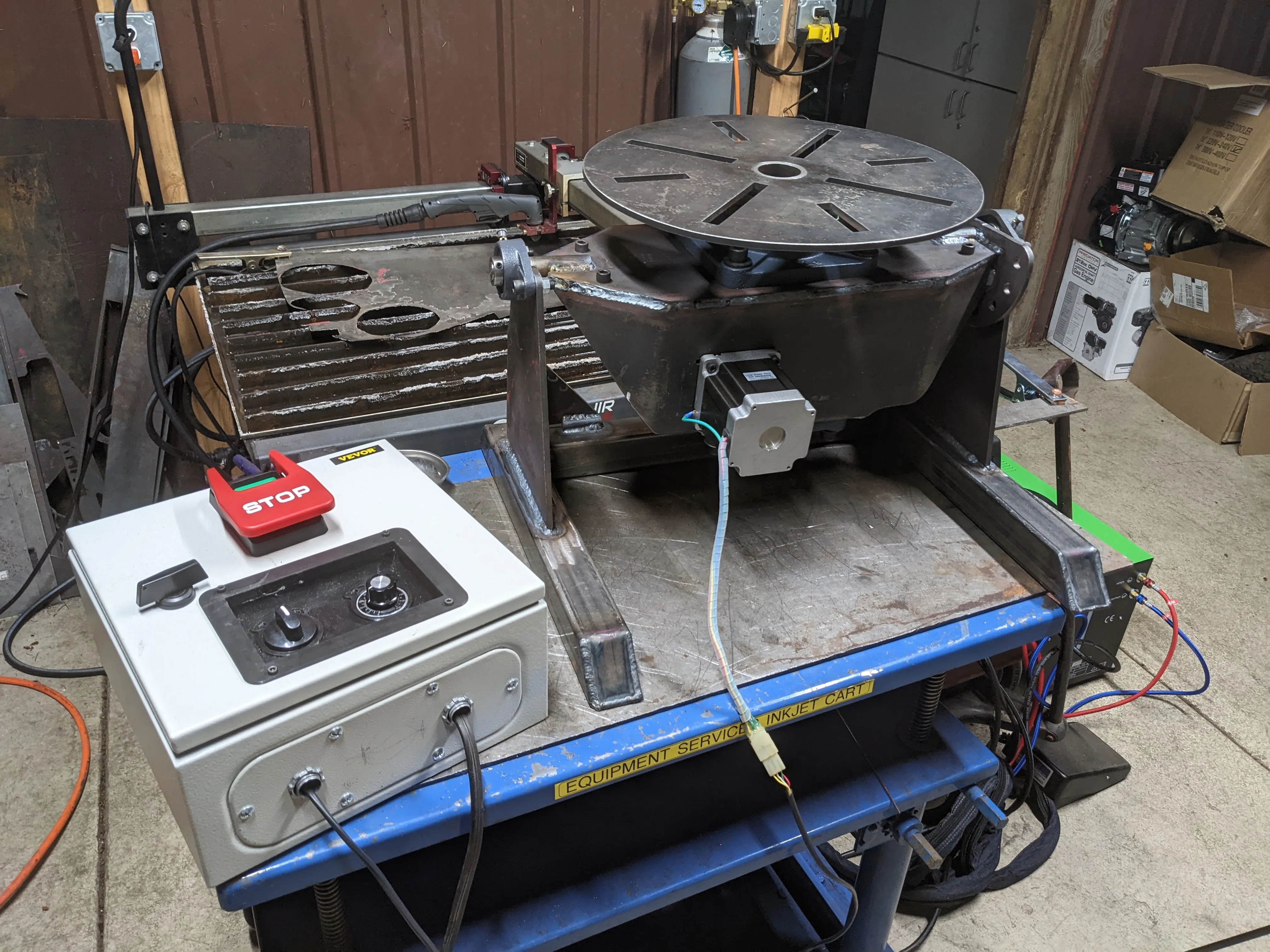
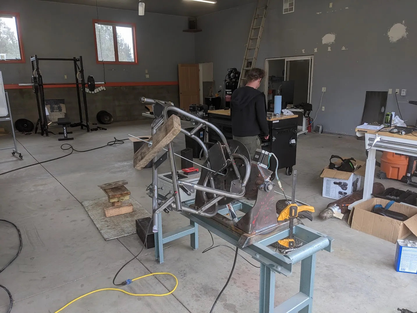
Many years later in 2026 I continue to use it for various tasks including repositoning for awkward-to-reach welds on a mini-bike frame (2023)
As well as continuous rotation for buildup of undersized bores (2026)
It never did end up getting a paint job…