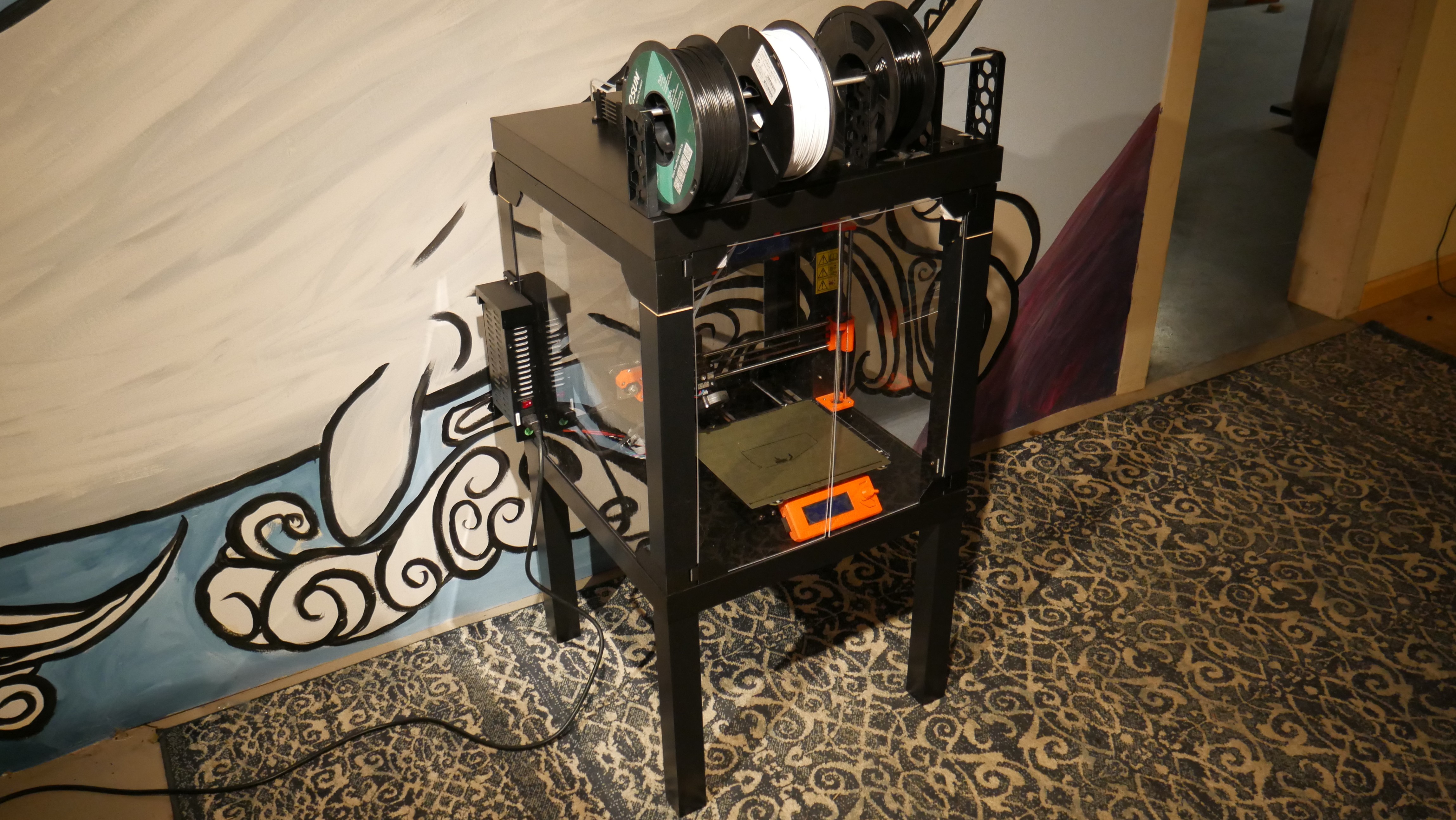
In this quick and dirty project we assemble the official Prusa mk3s enclosure
I lie, not quick, took months
Setting Clear Goals
- Intent: Clear off deskspace, bundle up printer, reduce noise, enable transport
- Publish: Share unintuitive gotchas
- Research: Been done, follow steps https://blog.prusaprinters.org/mmu2s-printer-enclosure_30215/
- Method: Repeat a previous build
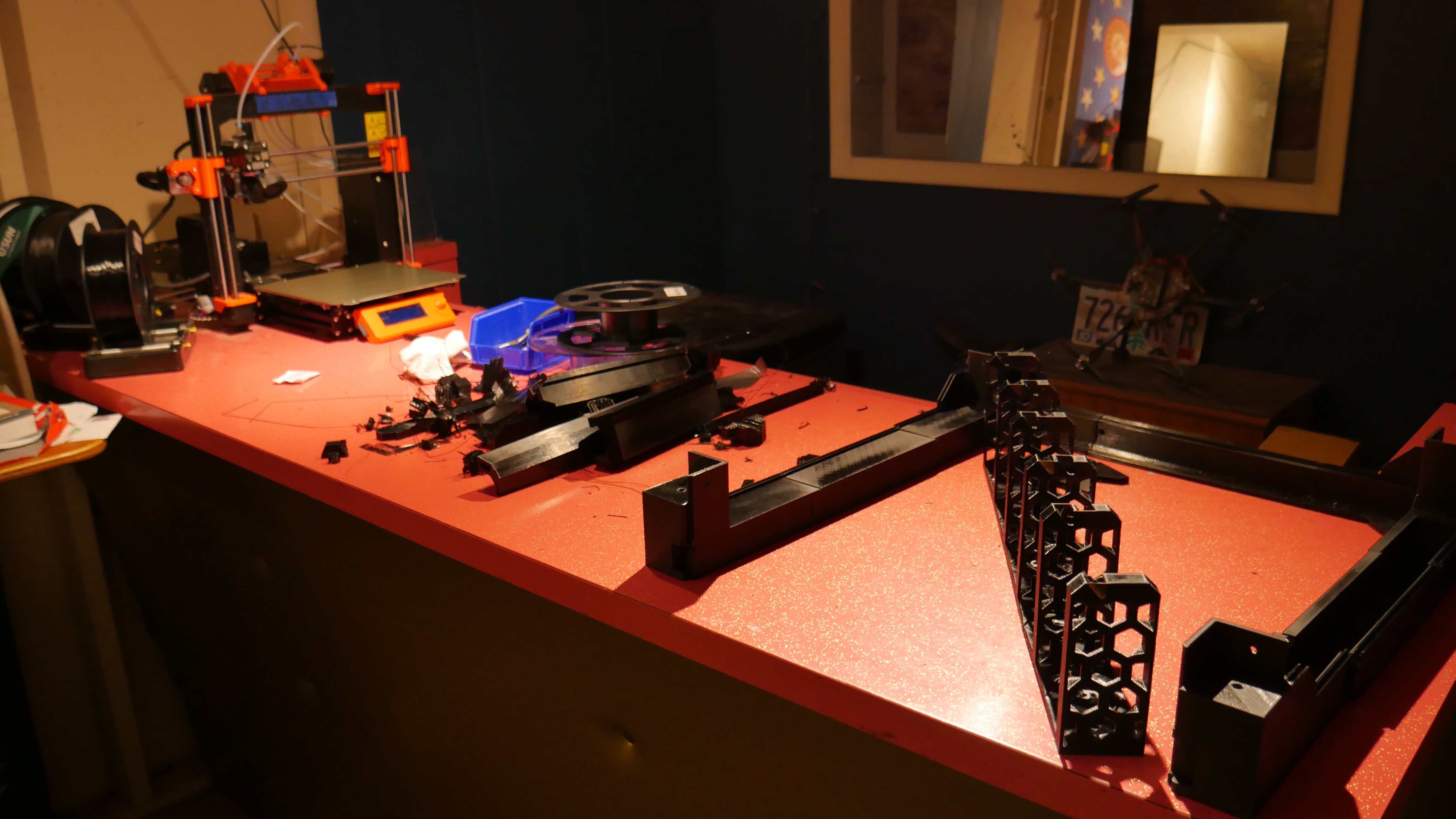
High lead time: Print Parts
Gonna go through all steps and print parts while I follow the instructions
Using 3mf model files for custom slicing on MMU Settings: default except use filament 5, PETG
#1 - Building the box, lower table
Using prusa_mmu_enclosure_1.3mf
- Prusa_MMU_enclosure_corner_bottom_front_right
- Prusa_MMU_enclosure_corner_bottom_front_left
- 2x Prusa_MMU_enclosure_corner_bottom_rear_left
- Prusa_MMU_enclosure_hinge_bottom_left
- Prusa_MMU_enclosure_hinge_bottom_right
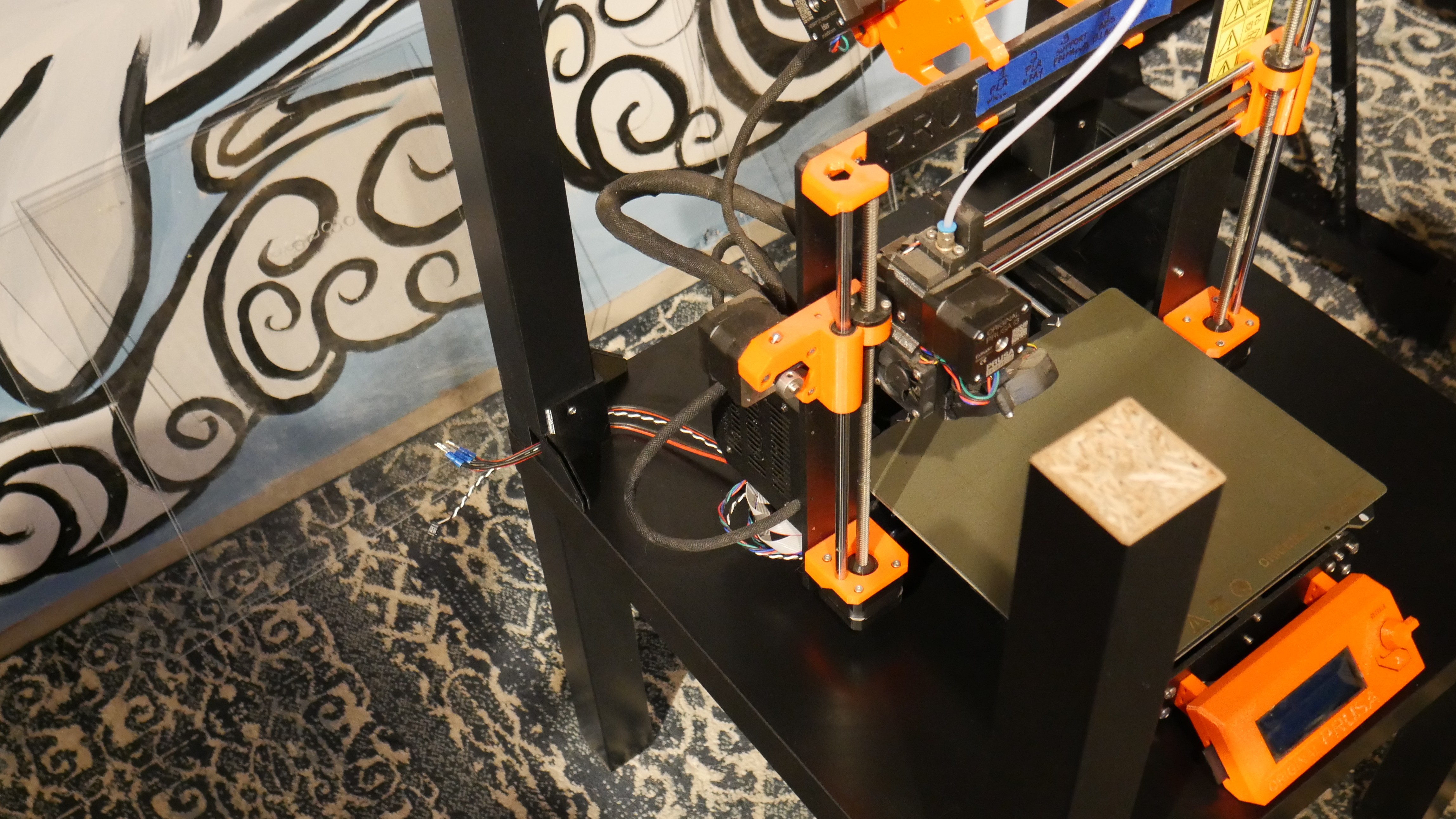
At this point I have already printed up to #7, and due to a pause the printer has been sitting for a month or two. The first layer of print #8 was smearing and not depositing (more on that later), so Z was live adjusted from .735 to .572. 20 hour print here we go!
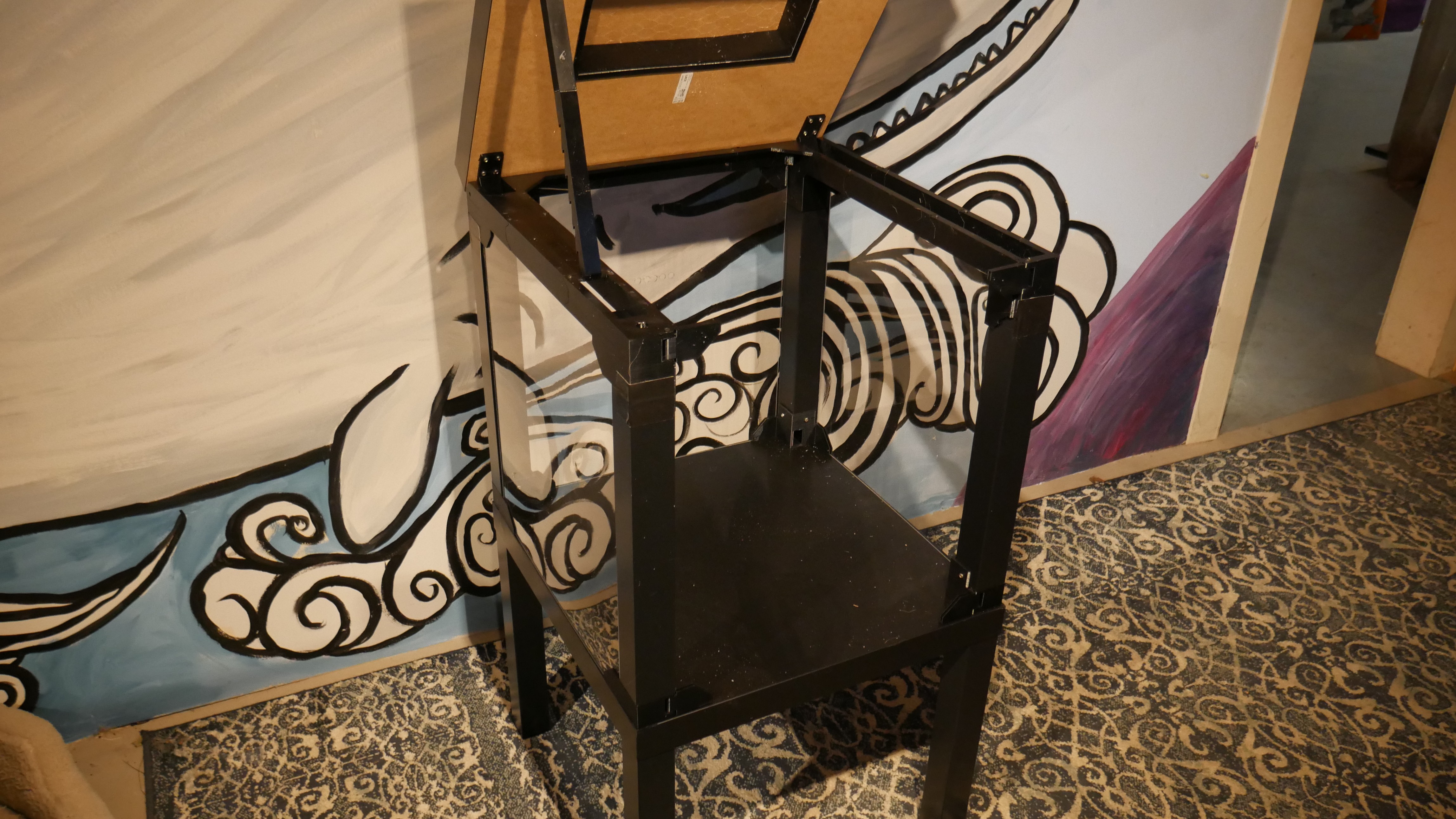
Unbox the Lack. Assembly tip: screw in the double lags to the table firmly first, otherwise it gets tippy
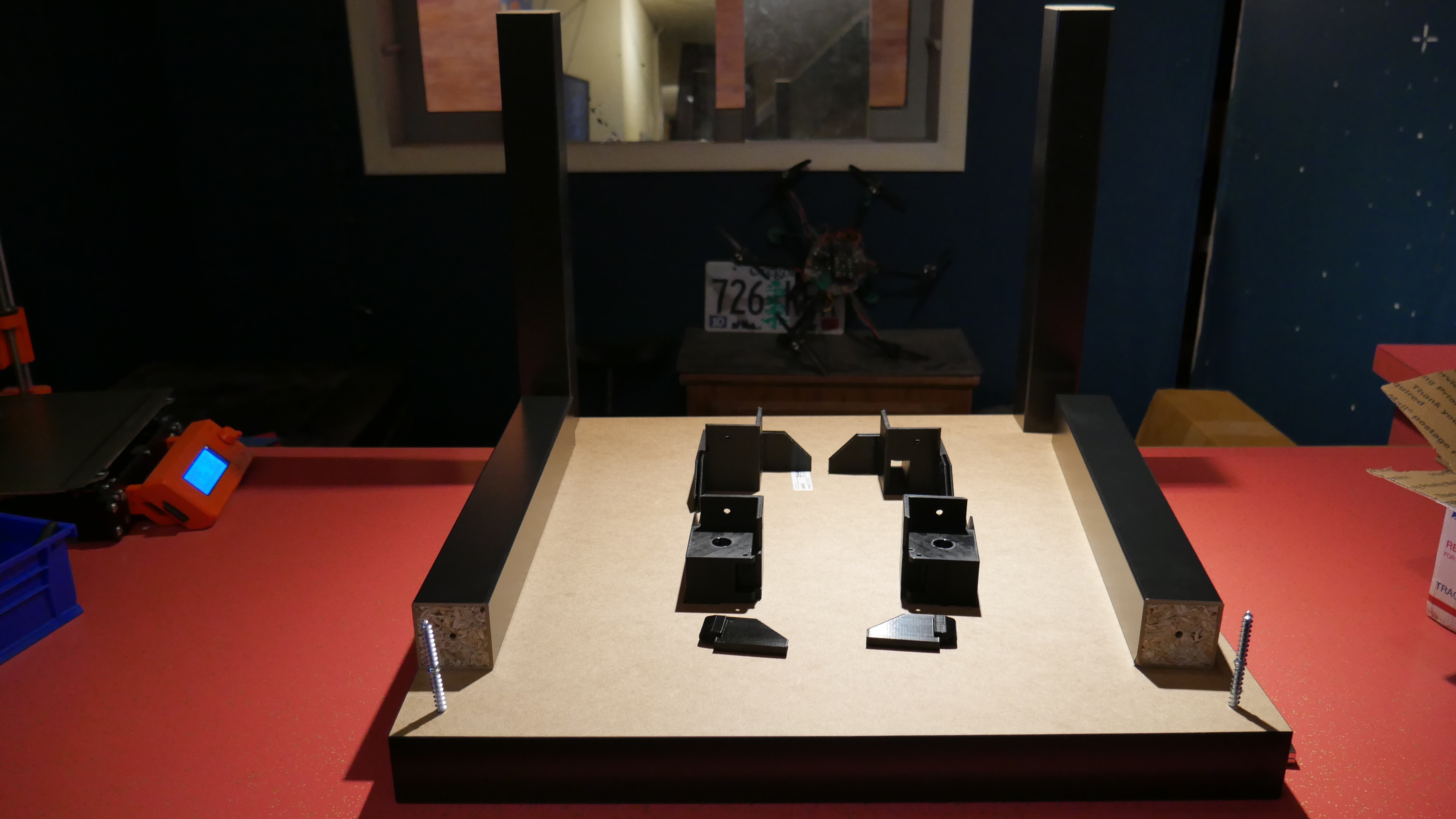
When inserting the M3x30 screws into the bottom corners I first pushed down from the top to pop out the supports, then reinserted them from the bottom. They do not fight tightly or thread, but they will be captured later.
To orient the magnets correctly I first stuck them together, then separated and inserted. This ensures they stick
When screwing down the corners I went until they started squeaking rather than until the impact driver started, this ensures the parts aren't destroyed by torque
Many of the thin guides on the corners of the parts broke when removing from the build platter, I aligned them by feel matching the inset from the table edge to the legs below
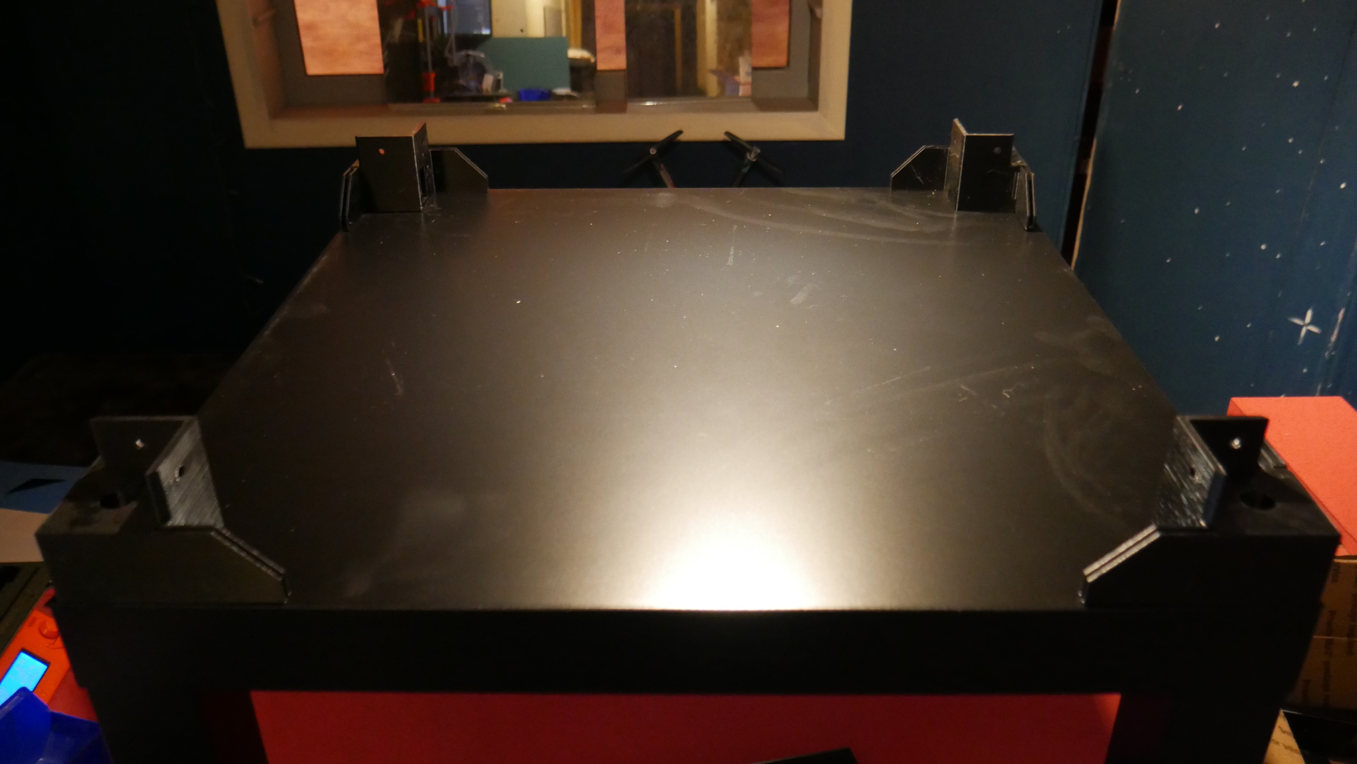
The legs were added with the table tipped on its side so I could screw downwards, the parts from step #2 provided the perfect spacer to make sure it was aligned. It's very important that shop operations are ergonomic, if you're comfortable it is much more likely that the result will be correct.
Note from the future:
Ensure that the legs are attached with the holes DOWNWARD! The holes in the legs are in the exact position that the M3x30 screws will be placed in step 9
In addition when replacing the screws I angled them slightly such that they tended to draw the legs into the corner as they tightened. This reduced wiggle

Another note from the future
Since I want to mount the power supply "above the waistline" I will be routing the cables out the corner. The cables exit the printer on the back left, thus ensure that the bracket with the hole through it is in that corner, not the back right cries in reassembly
#11 - Placing the power supply (black)
Print parts:
prusa_mmu_enclosure_11_black.3mf
- Prusa_MMU_enclosure_PSU_holder
- Prusa_MMU_enclosure_frame_brace
- Prusa_MMU_enclosure_cable_tube
As I am still using the printer to print parts I am skipping this step for now. It remains to be seen what the consequences of this are
#2 - Building the box, upper cover
Using prusa_mmu_enclosure_2.3mf
- 4 x Prusa_MMU_enclosure_top_desk_cover_a
- 2 x Prusa_MMU_enclosure_top_desk_cover_b
- 2 x Prusa_MMU_enclosure_top_desk_cover_c
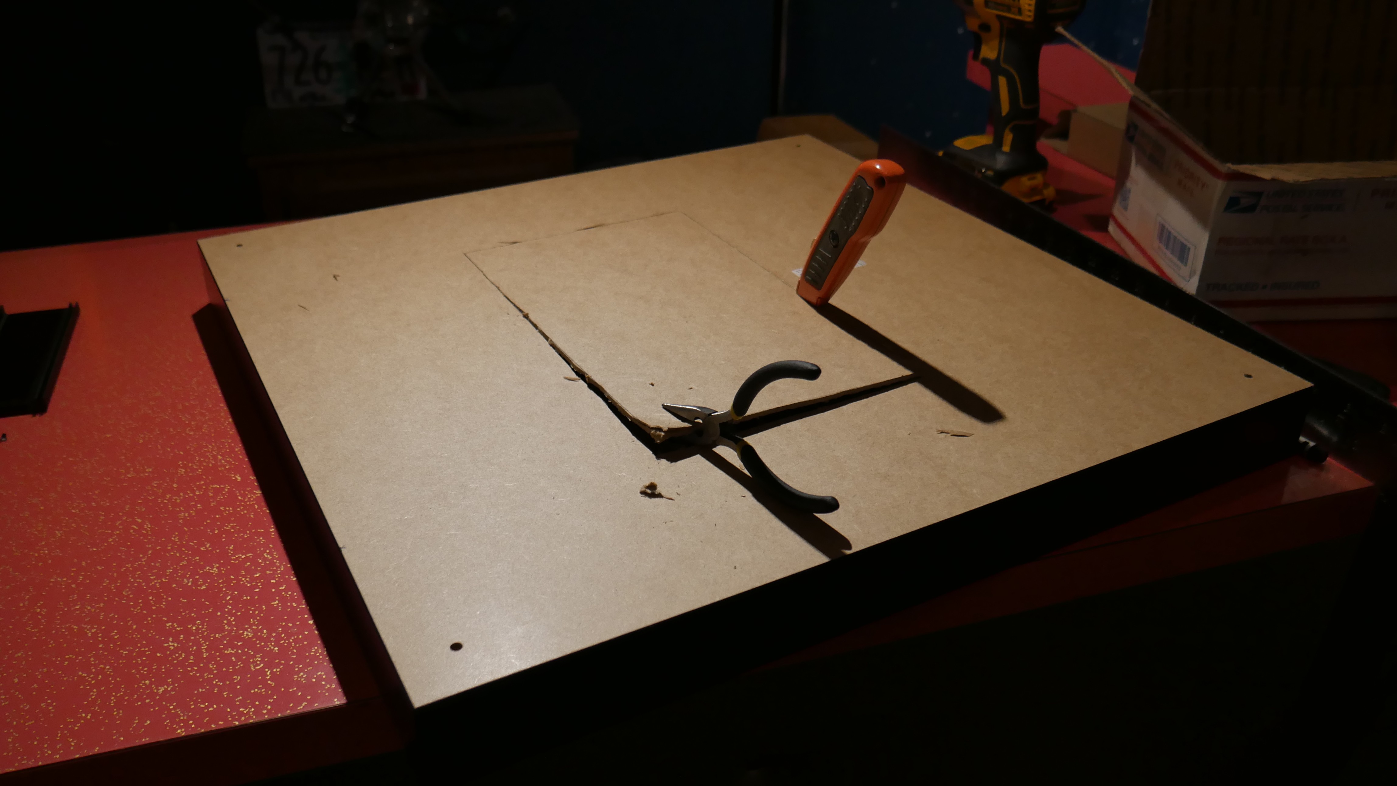
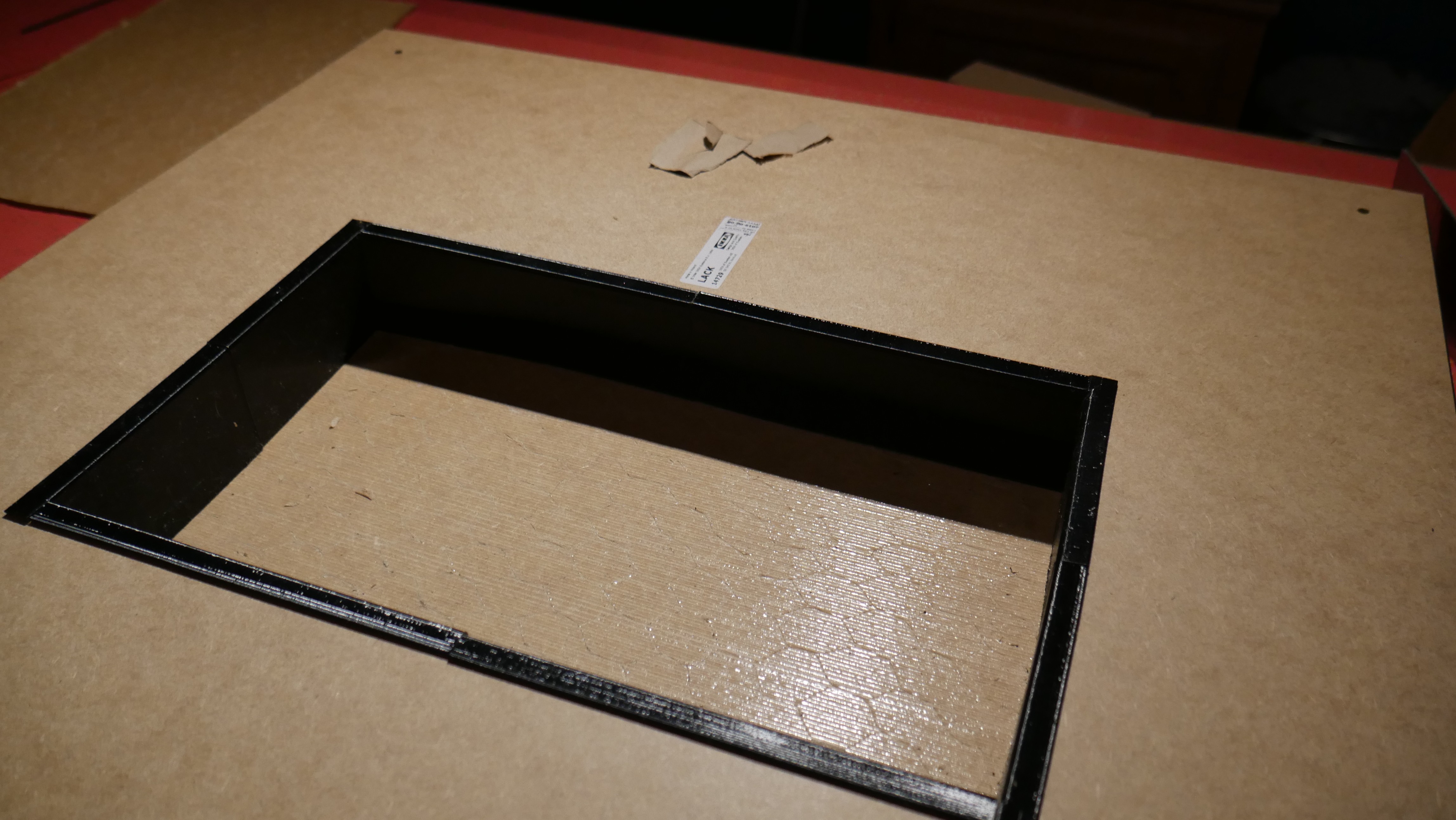
Measure, Hollow cover
The dimensions have been helpfully converted into decimal inches, unfortunately they must not realize the depths of insanity we operate under in the US. Below I have converted the decimal inches to the nearest 1/16th in order to use our standard fractional measuring tools
| mm | in(d) | in(f) |
|---|---|---|
| 120 | 4.7 | 4-3/4 |
| 310 | 12.2 | 12-3/16 |
| 170 | 6.7 | 6-11/16 |
| 180 | 7.1 | 7-1/16 |
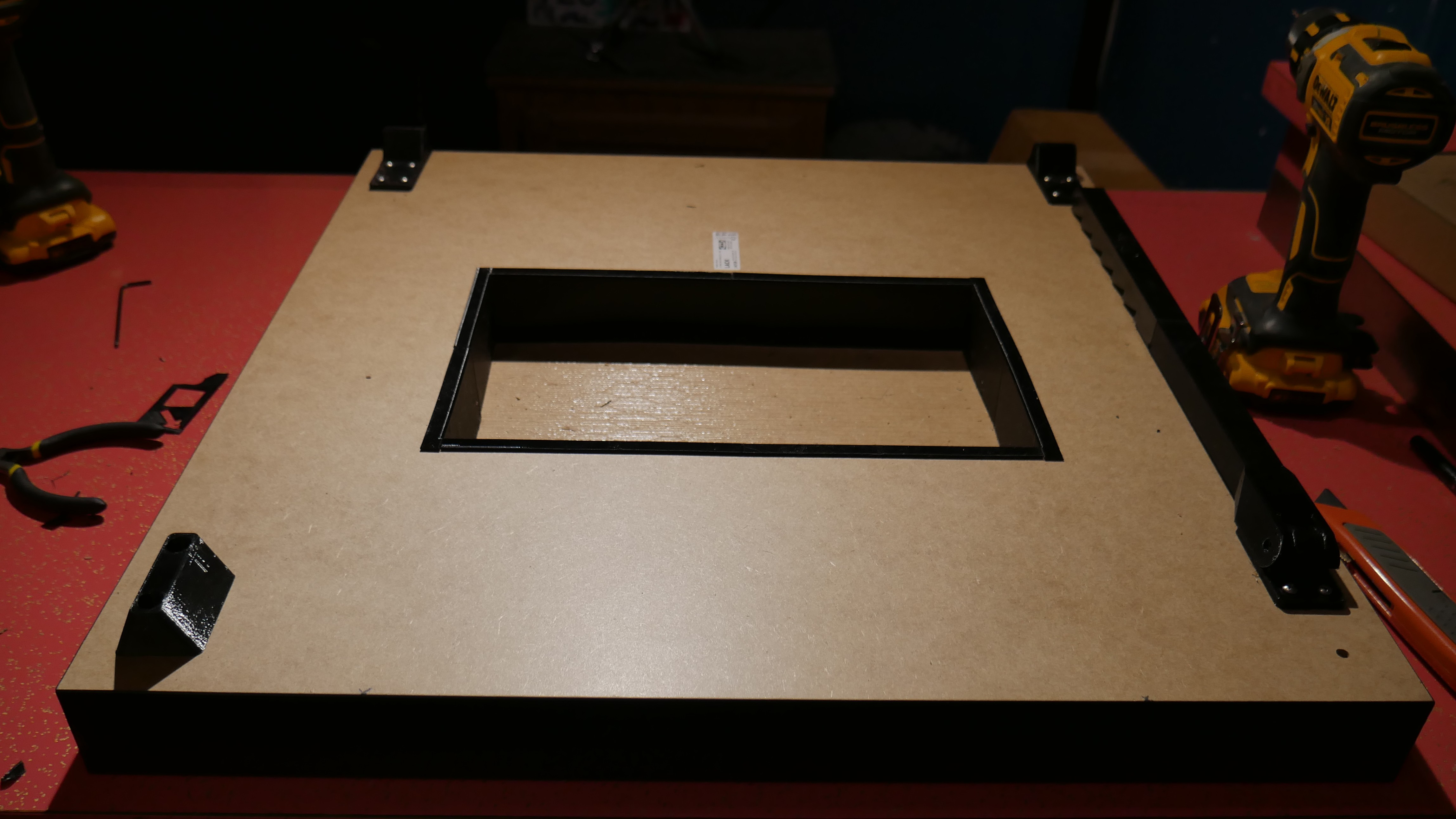
It's important that the short sides are installed first, they fit into the corners and the long sides fit over them.
#3 - Supporting arm
prusa_mmu_enclosure_3.3mf
- Prusa_MMU_enclosure_support_arm_base
- Prusa_MMU_enclosure_support_arm_a
- Prusa_MMU_enclosure_support_arm_b
Note hinge orientation for edge
A 5/64 drill is very similar to the 2mm drill they specify
One of the holes in the supporting arm brackets was located over one of the pre-drilled holes in the table. I shifted it a couple mm to give clearance
#4 - Hinges supporting arms centering cap
prusa_mmu_enclosure_5.3mf
- Prusa_MMU_enclosure_centering_part
- Prusa_MMU_enclosure_top_desk_hinge_right
- Prusa_MMU_enclosure_top_desk_hinge_left
Note top edge of hole
#6 - Prep rear sheet
I bought the closest sheets I could at the local hardware store, which ended up being 0.100" thick. this is similar to 2.5mm
Raw sheets: 0.100x30x36" and 0.100x28x30" Requirements:
- 3x 440x473mm -> 17.3228x18.622" -> 17-5/16x18-5/8"
- 2x 220x505mm -> 8.66142x19.8819 -> 8-11/16x19-7/8"
Converting back from fractional inches to mm results in an error < 1mm
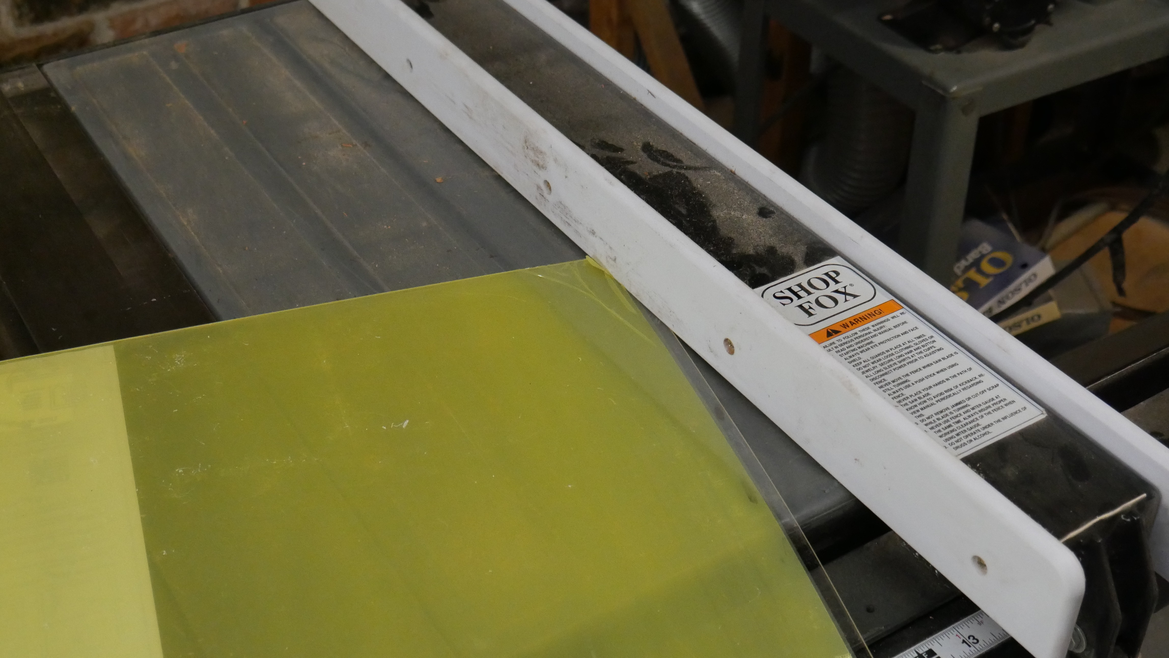
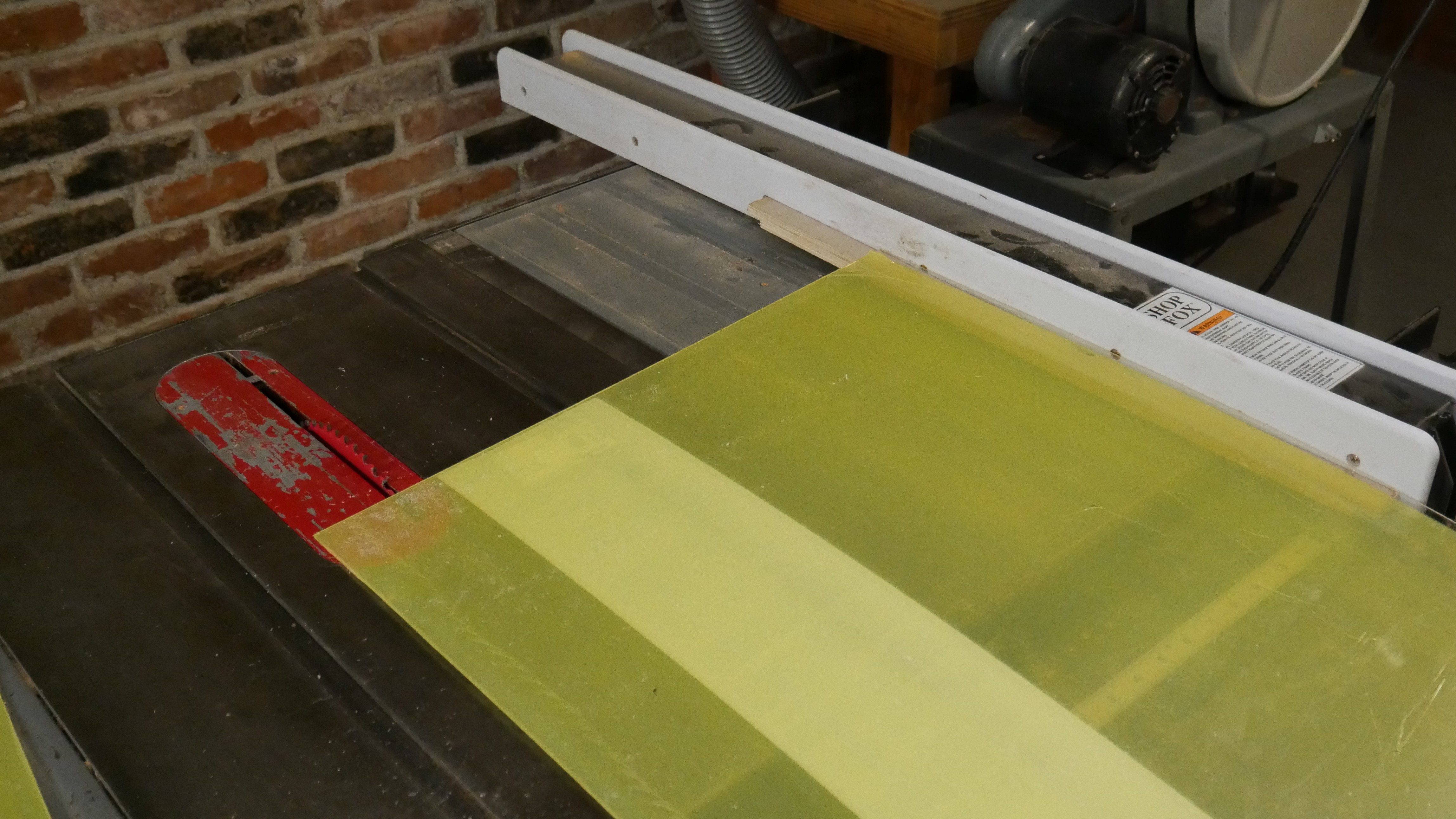
First I laid out the dimensions on the plastic sheet over the plexiglass
And using a fresh blade I cut the shapes out on a tablesaw. A skill saw and fence could be used (see my fence guide project - TODO: link when done), though if the tool is available why not use it!
I used a new 60T diablo saw, going with a higher tooth count for a finer finish.
During cutting the sheet was going underneath the fence on the table saw, I put a piece of plywood underneath it because the cosine error is not significant.
During cutting measurements were taken many times on the same features:
- During initial layout
- Verification after layout complete
- Setting table saw fence to a specific number and comparing to layout (if not using table saw sled -- TODO: put measurements on sled)
- After cutting verifying the measurement is correct
- Checking squareness against reference
- Checking parts against each other
In addition measurements were made with different methods each time, thus ensuring the highest chance of catching any issues.
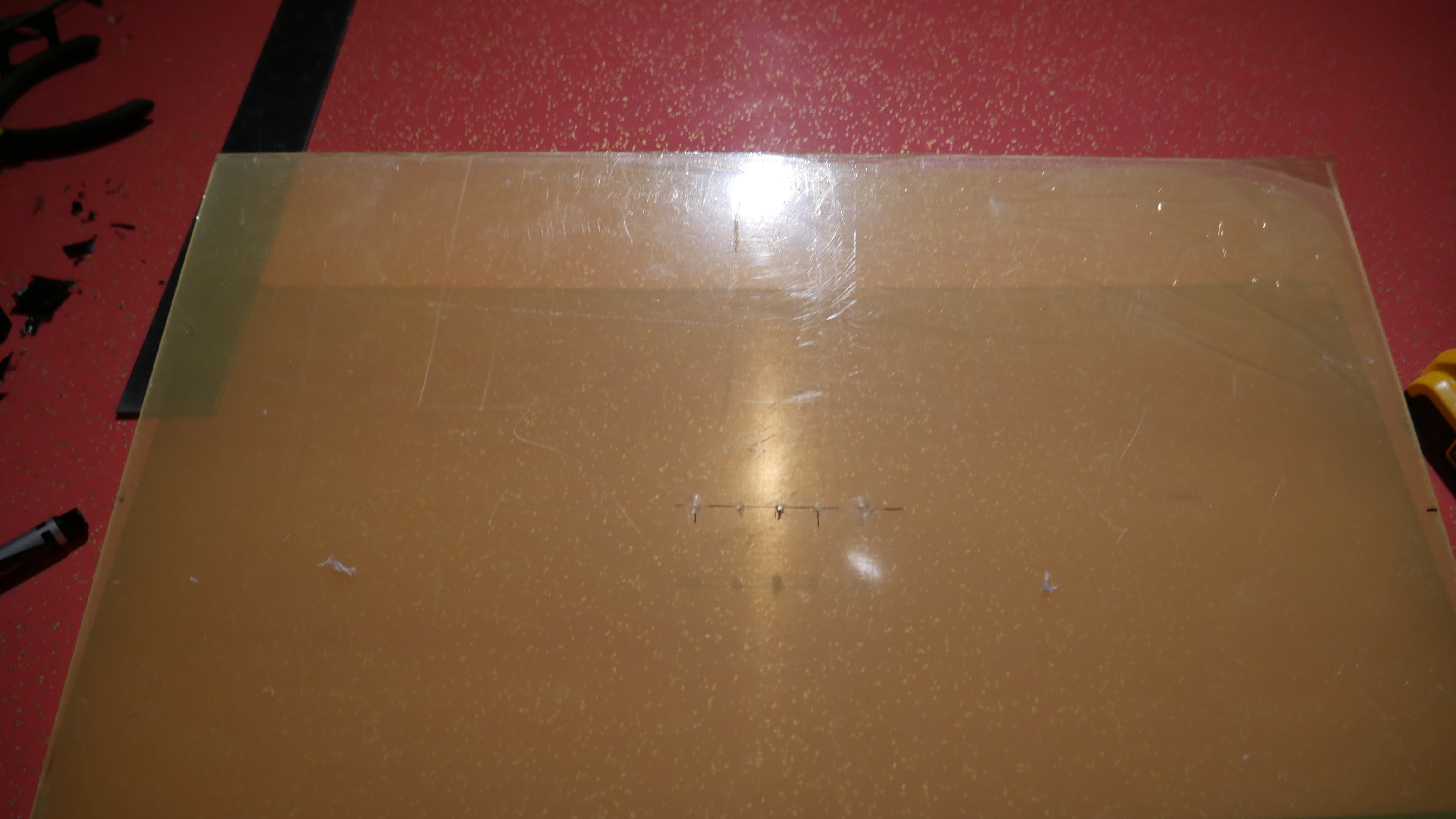
Putting the 5 PTFE tube holes 320mm (12-5/8") from the bottom and 15mm (9/16") apart. The sheet is 17-5/16 wide, thus 8-11/16" from the edge.
First use the 5/64" drill to pilot drill all of the holes
My closest fractional drill to 10mm (0.393") is 3/8" (0.375, 9.5mm)
Using several intermediate drills work up to the final size.
My sequence was:
- 5/64"
- 5/32"
- 1/4"
- 3/8"
#7- Assembling U-frame
After an agonizing week of near constant printing and some failed prints the last parts were finally printed

There were a few causes of these prints:
- The hotend got globbed up with goopy PETG and kept scraping up the first layer
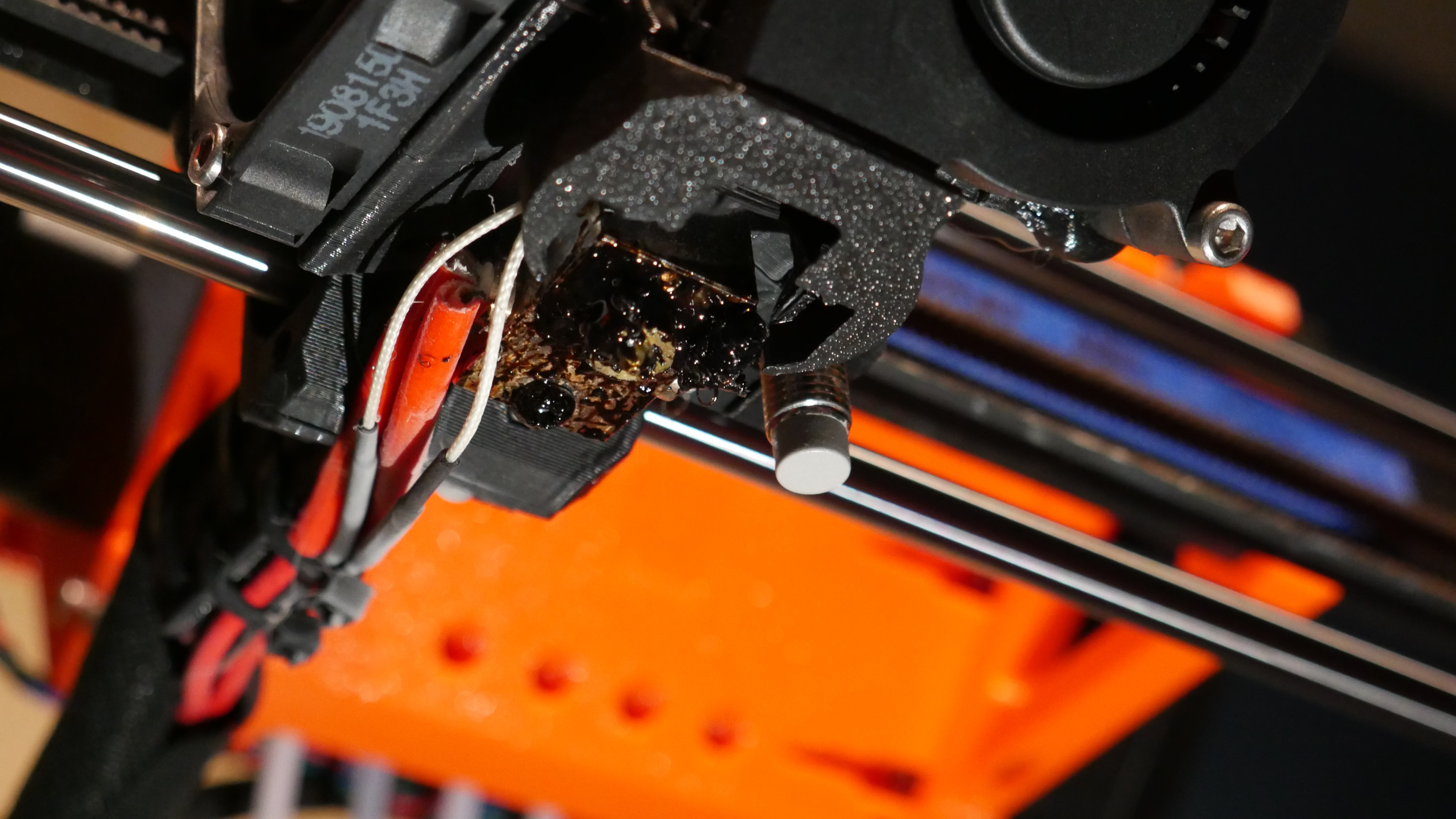
- A kink on the end of the spool caused the filament to stop feeding between changing filaments, missing a layer or two of the print. This caused all of the prints to separate on that Z layer
- Lack of lubrication or a power outage (unknown which) caused the printer to skip steps, causing a layer misalignment
- Prusa_MMU_enclosure_corner_top_front_right
- Prusa_MMU_enclosure_corner_top_front_left
- Prusa_MMU_enclosure_corner_top_rear_right
- Prusa_MMU_enclosure_corner_top_rear_left
- Prusa_MMU_enclosure_middle_part_back
- Prusa_MMU_enclosure_middle_part_right
- Prusa_MMU_enclosure_middle_part_left
- Prusa_MMU_enclosure_hinge_top_left
- Prusa_MMU_enclosure_hinge_top_right
The bottoms of the prints were missing clearance holes for the heads of the Socket Head Cap Screws, so I used a 3/16" drill to clear them out by hand.
#8 - Attaching the acrylic sheet windows
No plexi extension, cut the panels from scratch.
Assembling the windows was fast and went without issue thanks to the accurate dimensions
#9 - Attaching the top cover
Attaching the top cover went quickly, though it was at this time that issues were discovered as reported in earler steps.
#10 - Attaching the door panels
Some paper was used to shim the door panels into place as the plexiglass is thinner than the prints were designed for
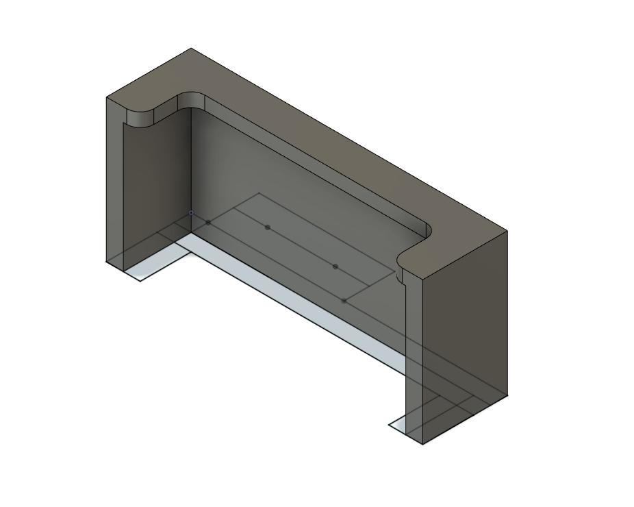
#11 (continued) - Making an alternative power supply mount
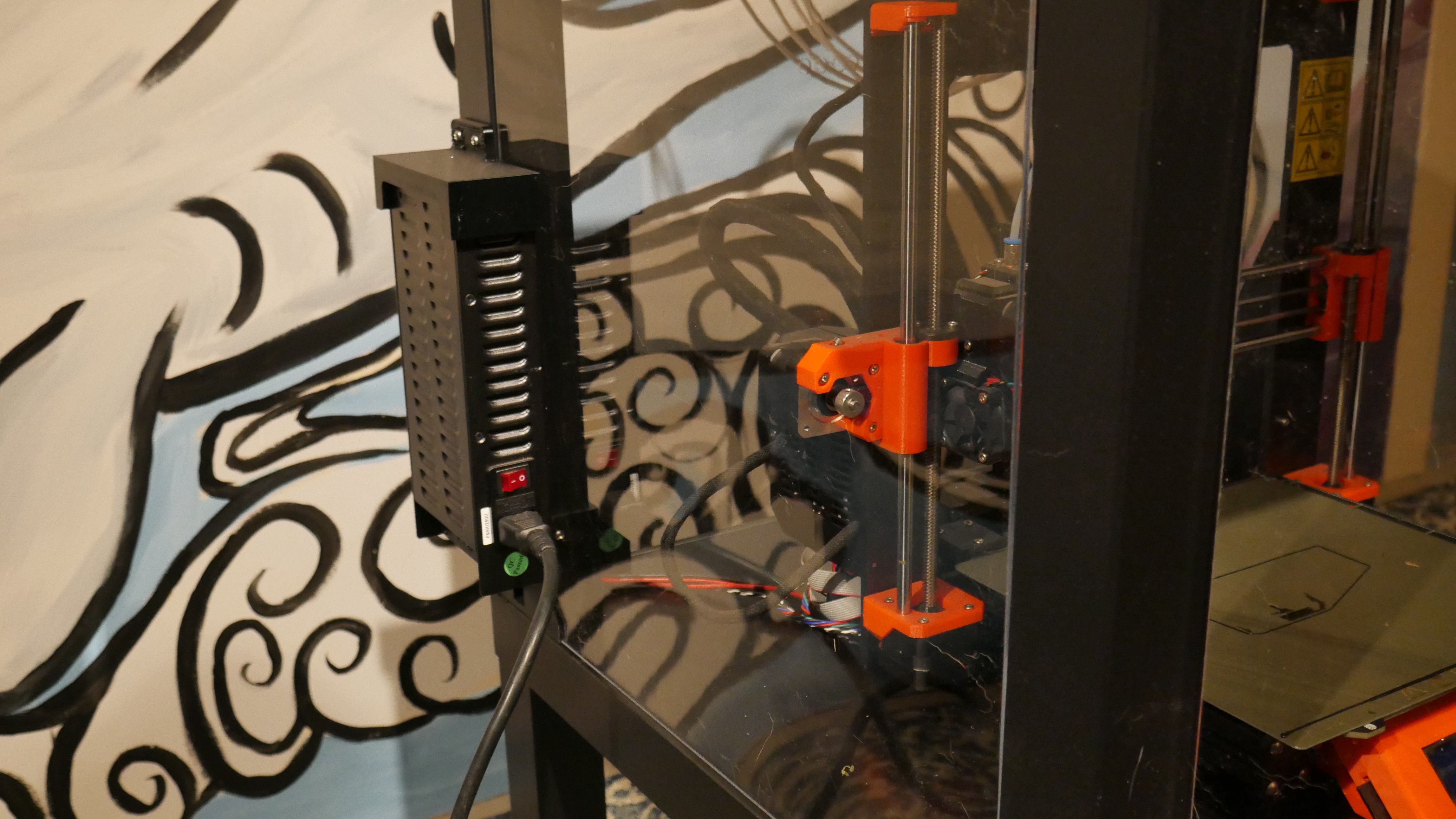
Done
The final result is pretty neat looking if I do say so myself