3d printing allows quickly iterating on taking assembly issues and applying them to the design
Motor Arm Issues found
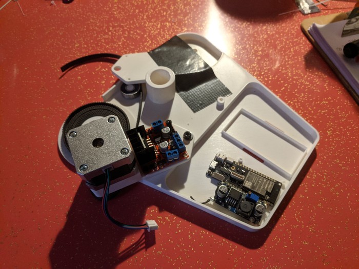
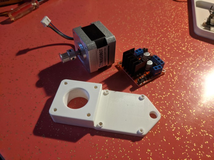
The first and most major issue was that the motor arm had several oversights due to a desire to get the first draft printed.
Specific fixes include:
- Enlarging the motor hole - I guessed a dimension that turned out to be inaccurate and did not update it when the part was in hand
- Adding space for the motor shaft - The motor required being stood off from the spool. Rather than shortening the motor shaft a block was added
- Stepper driver standoff - the stepper driver had standoffs added to give clearance to the pins extending from the bottom of bord
Spool tensioning
The spool ended up way too small due to underestimating how much space the entire belt would take. In addition a feature was added to capture the start of the belt.
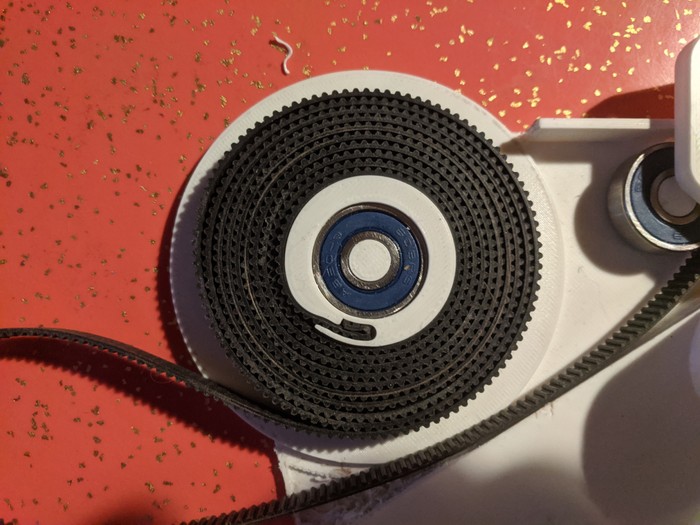
One needed refinement is to reduce the abrupt bump when the belt wraps over itself the first time. Still working on that...
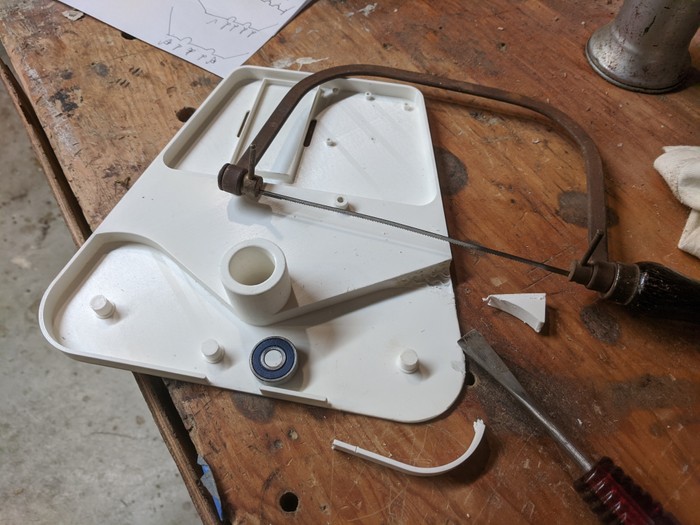
Wood... working?
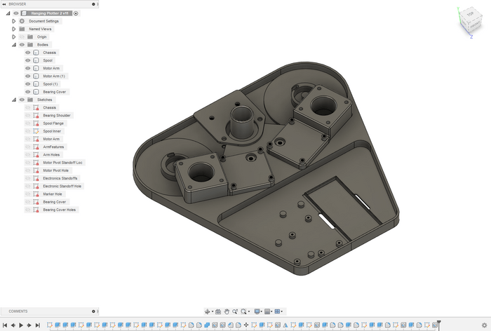
Since the size of the spool increased dramatically the chassis had some extra plastic interfering with mounting everything. Rather than running another 8 hour print a bit of cross-diciplinary modification was made...
Construction drawings
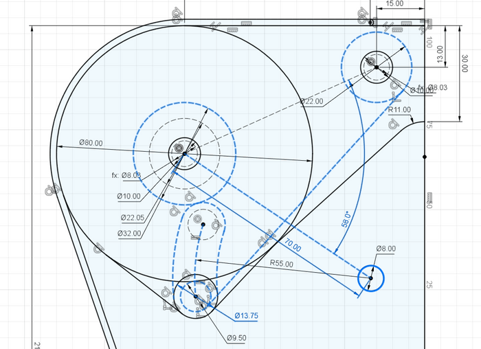
One of my favorite aspects of parametric modeling is figuring out exactly WHY parts relate to each other and dimensioning that. Sure measuring 10mm from the top or 5mm from the bottom might produce the same end result, but more accurately the feature might be located tangent to a line projected from some other aspect of the drawing.
The belt running from the motor to the pivot bearing ended up interfering with the spooled belt. Using some construction drawings the geometry of the motor arm was refined to allow free motion:
Another Reprint?
Since the first set of iterations resulted in something that connected motor to belt and allowed the electronics to mount there is no need to reprint with additional refinements until the functionality is tested.
